Deep drawing process optimization
Why?
Deep drawing is a metal forming process used to make hollow parts in the shape of a box or a cup from flat sheet metal called the initial blank. During the process, the blank is plastically deformed into the final shape, causing uneven height variation along the flange due to orthotropic material properties.
This project focuses on optimizing the initial blank contour to form a cylindrical cup, with the objective of minimizing height variation along the cup flange, commonly known as earing.
Earing occurs primarily due to material orthotropy introduced during the sheet metal production process (rolling), which causes uneven plastic flow in different directions. This defect leads to:
-
Increased trimming requirements, resulting in material waste
-
Higher manufacturing cost and cycle time
By optimizing the blank shape, the non-uniform deformation caused by orthotropy can be compensated before forming, reducing or eliminating earing without changing the material or tooling, which is highly attractive for industrial production.
What?
This project delivers a MATLAB-based optimization tool designed to identify an optimal initial blank contour for the deep drawing of a cylindrical cup. The application couples optimization algorithms with a parameterized finite element model to automatically modify the blank geometry and evaluate flange height variation. By iteratively minimizing earing, the tool provides an efficient and practical solution for compensating material orthotropy without changes to material properties or tooling.
How?
The optimization is carried out through a simulation-driven and an iterative approach using optimization algorithms.
Let’s explain the standard and the parameterized/scripted modelling process.
Standard finite element modelling
Create an FE model that simulates the deep drawing process. Tasks include the definition of:
-
Deep drawing press geometry
-
Initial blank geometry
-
Material models
-
Contact parameters
-
Boundary conditions
-
Meshing parameters
-
Solver settings
Deep Drawing Simulation
Once the FE model is ready, it’s time to simulate the process which consists of:
-
Force is applied to the blank through the blank holder
-
The punch moves downwards and presses the blank into the die
-
The punch moves and deforms the blank into the cup shape
Once the punch has passed through, it’s possible to quantify flange height variation, and thereby, identify regions of excessive or insufficient material flow and modify the blank to compensate for it.
Due to symmetry and to save computing time, only a quarter of the model was simulated with appropriate boundary conditions.
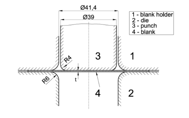
Figure 1. Tool information
|
|
Figure 2. FE simulation of deep drawing process
|
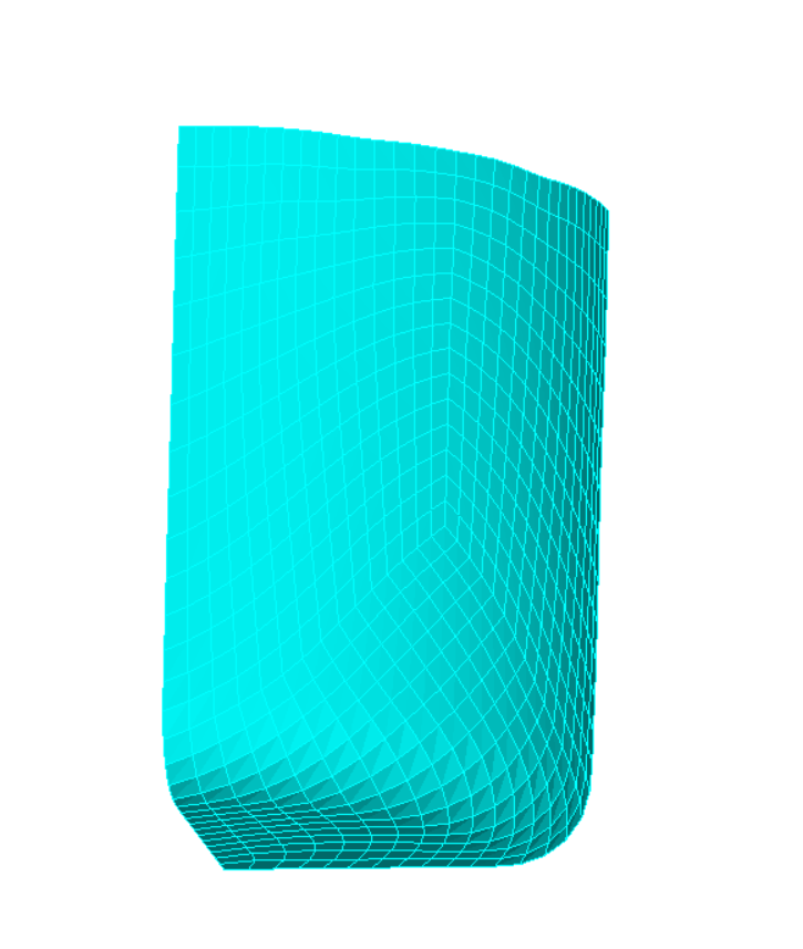
Figure 3. Deformed cup
|
Blank Shape Modification
In the literature, there are a few different proposals that use the Lankford parameter (R-value) to adjust the blank contour (e.g., lobed, elliptical, or spline-based shapes) to minimize earing.
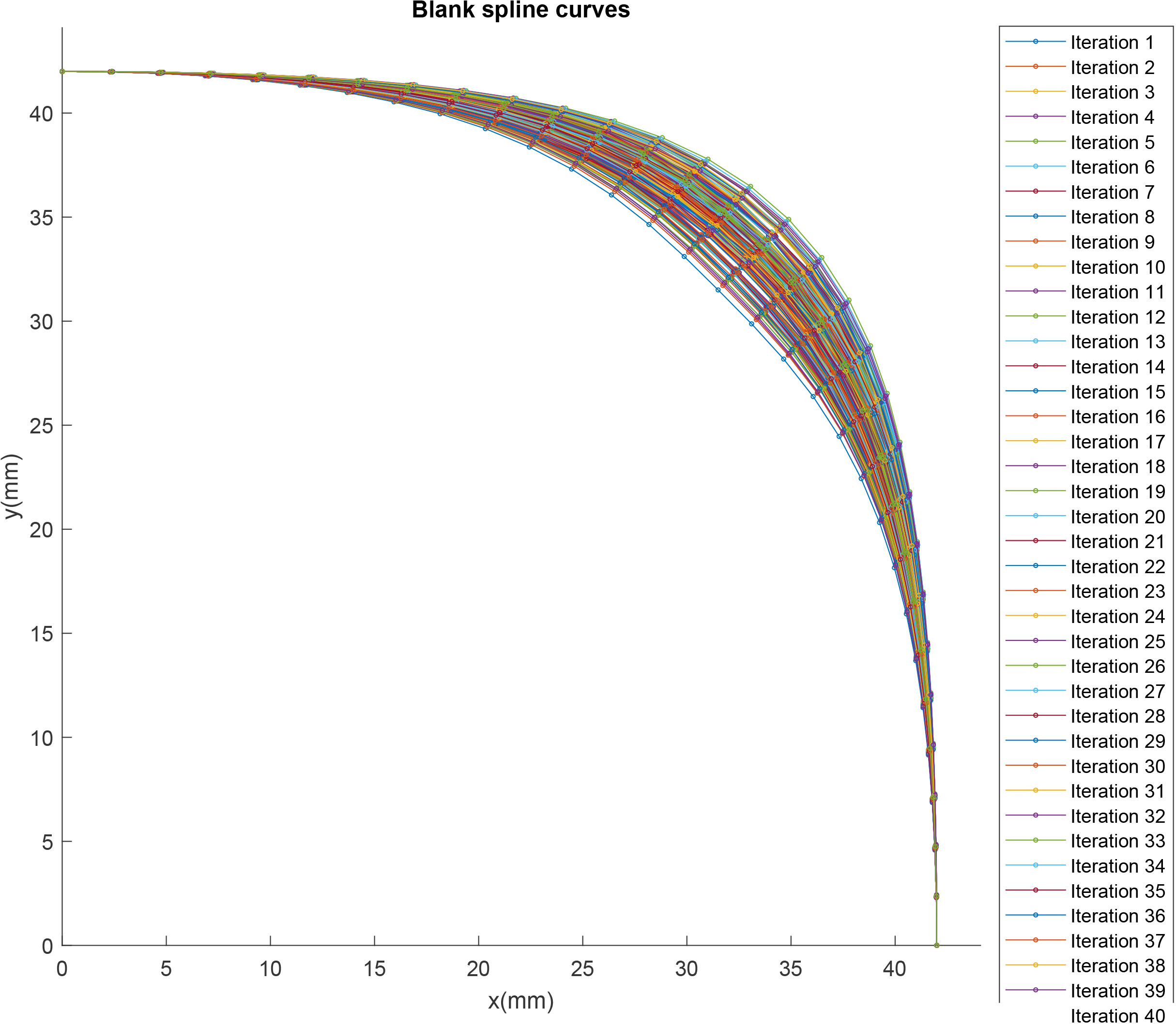
This project uses a B-spline-based definition with 5 points (x, y) to describe the blank contour. Despite having only 10 real variables, this problem is difficult to tackle by simulating all possible combinations. This is also the reason why optimization methods are used to find the best solution.
The figure below shows an example of the flexibility provided when the blank contour is defined using a spline.
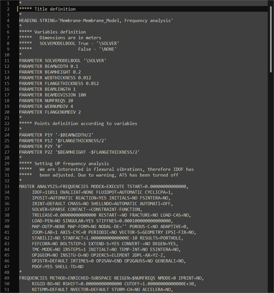
Script-based finite element modeling
Creating FE models and post-processing the results cannot be done by hand, as it would require a significant amount of manual effort. Therefore, script-based FE model creation is automated using values provided by the optimization algorithm. Additionally, another script is used to obtain the height difference along the cup flange.
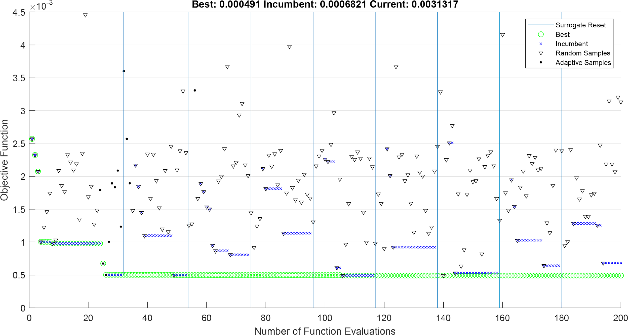
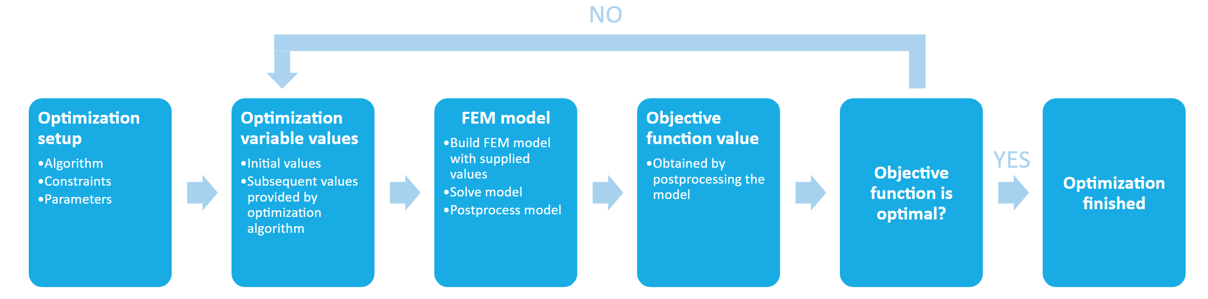
Optimization Process
With all components ready, a pipeline is built that enables communication between the script-based FE model and the optimization algorithm, exchanging values of the objective function and optimization variables. The optimization process is shown in the image below.
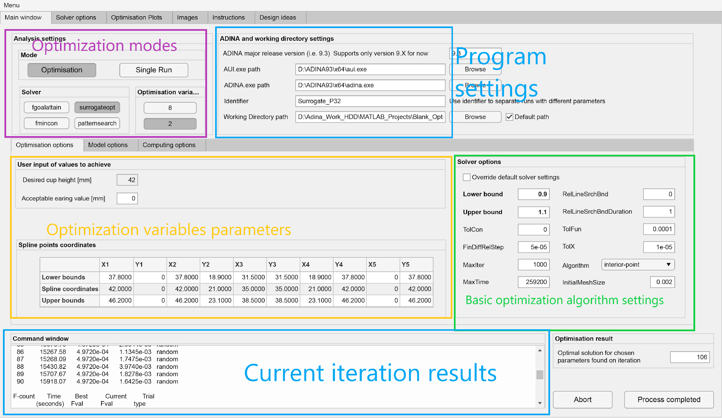
MATLAB application
An app with a UI was developed to help find an optimized solution for a cup of a specific height and diameter.
Features:
-
Single and multi-objective optimization
-
Highly customizable optimization algorithm settings
-
Support for optimization in parallel
-
Support for specifying the CPU core count for FE computation
-
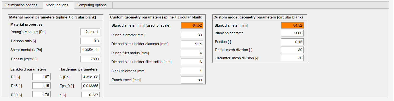
Parameterized FE model creation (including the tool geometry)
-
Post-processed results per iteration available within the tool
-
Objective and optimization variable values
-
Spline coordinates for an optimized initial blank
-
Initial blank and cup height contour
-
Screenshot of a deformed cup from the FE tool
-