Image to ADINA
Why?
For fun! This is a small project made to show the automation capabilities and an understanding of solid mechanics and FE software by reproducing an actual picture.
What?
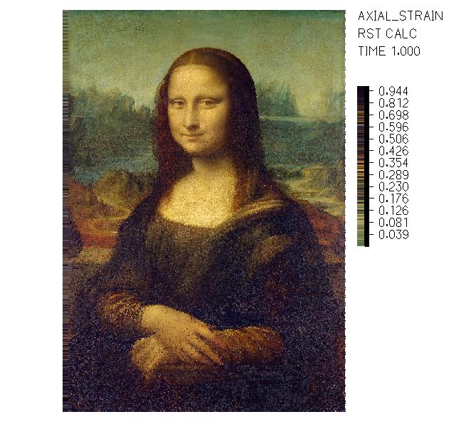
This script takes an image and creates a script-based FE file with its standard definitions: geometry, material, loads, boundary conditions and solver settings. It also creates a special colormap that matches the deformations of each truss element to the RGB value of the corresponding pixel of the image.
How?
With script-based finite element modeling, it’s possible to create an input file that can be read by the FE software. A 2D grid of truss elements is created to match the pixel dimensions of the image. Each truss has a unique length, and a prescribed displacement so that all of them have the exact same length in their deformed state. This allows the deformation of each truss to be mapped to the RGB value of the corresponding pixel in the image. To match the deformations and colors, a custom colormap is created and applied in the post-processing stage.