Modal and experimental modal analysis (EMA) of insulation floors
Why?
Numerical simulations are commonly used to predict how engineering structures behave, but they must be checked against real measurements to be reliable. In this project, validation ensures that the numerical model accurately represents the vibration behavior of ship insulation floors.
Structural vibration from onboard machinery propagates through the floors to the passengers on board. By validating the simulation model with experimental results, confidence is gained that it can be reliably used for further analysis.
What?
The validation focuses on checking whether the simulation and the real structure behave similarly when they vibrate. This is done by comparing key dynamic properties such as natural frequencies, mode shapes, and damping.
A numerical model of the insulation floor was created using the Finite Element Method (FEM) and analyzed to predict these properties. At the same time, experimental tests were carried out on the real structure to measure the same quantities. The comparison showed that the differences between the numerical and experimental results for the first six vibration modes were less than 5%, which indicates good FE modelling practices.
How?
The validation was performed by combining simulation and physical testing in a step-by-step process.
First, an FE model of the insulation floor was built in ADINA and used to predict its vibration behavior. The model was then gradually improved by adding more assumptions. After each improvement, the simulation results were compared with experimental data to reduce the differences.
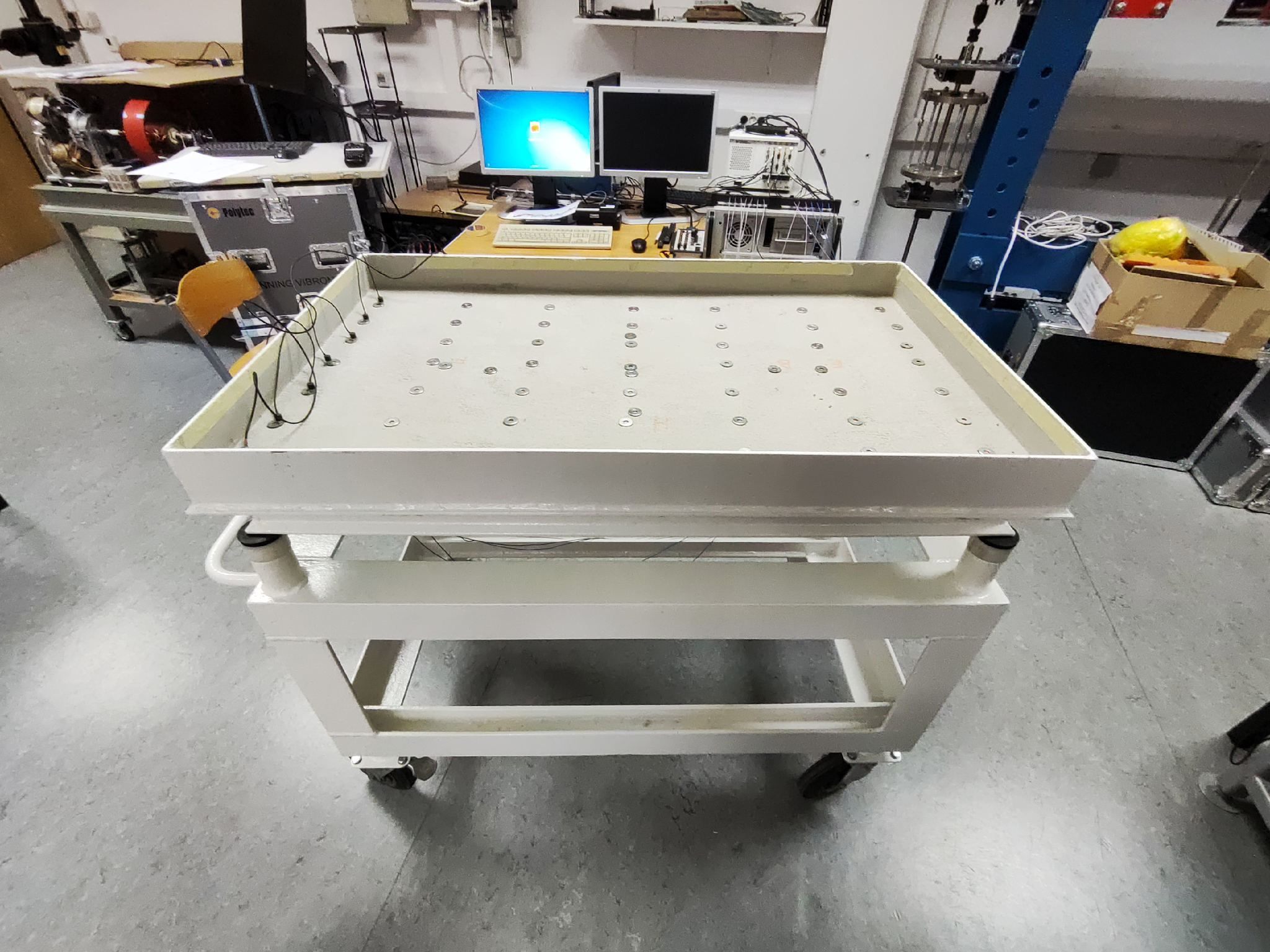
For the experimental part, the structure was excited using a shaker, and its response was measured with accelerometers. The measured data were processed using ME’Scope to identify natural frequencies, mode shapes, and damping. Finally, the numerical and experimental results were compared, confirming that the refined simulation model accurately represented the real system.